Verification of SCD files for digital substations: requirements and practical experience
This paper describes the fundamentals and practical experience of performing analysis and quality assurance of SCL files for digital substations. The basic requirements for visualization of SCD files, verification and detailed analysis of IEC 61850-based data exchange are presented.
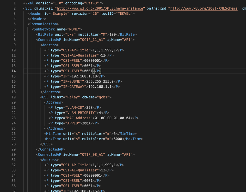
The IEC 61850 standard defines data models, communication services, and language and process for configuring intelligent electronic devices (IEDs). It defines three types of engineering software tools and six types of SCL (System Configuration Language) configuration files that are created during the design phase. Humans can read SCL files, but simple reading does not give a complete and accurate understanding of the operation of relay protection and automation systems and process control systems. Existing IED configuration software can provide some visualization of the contents of SCL files - though not at required level of detail and clarity (Fig. 1). Also, most of these programs are designed and intended for configuring IEDs from a particular manufacturer. This makes it impossible or extremely difficult to visualize and analyze SCL files for multi-vendor projects. In addition, the basic principles of quality assurance call for the use of tools other than those used originally to develop technical solutions when checking and verifying these technical solutions, otherwise errors made during the design can be left undiscovered.
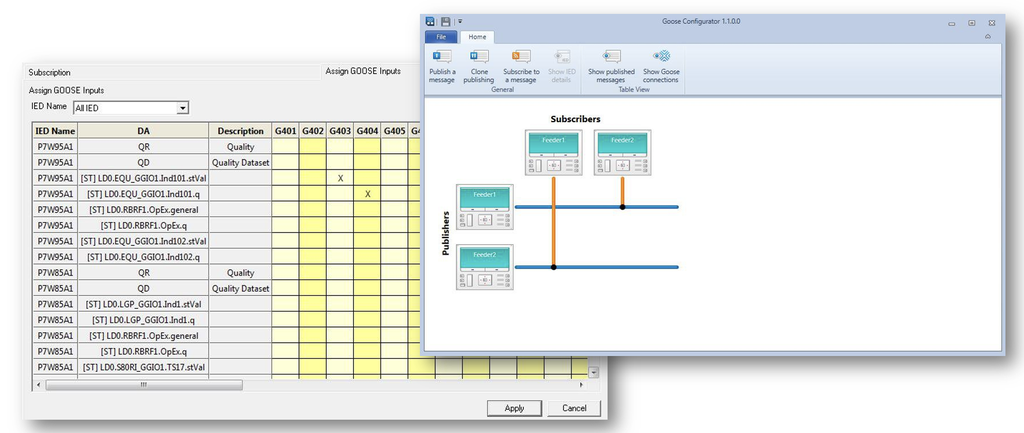 Fig. 1. Examples of SCD files visualization by IED configuration tools.
In ongoing projects, signal exchange according to the GOOSE, Sampled Values and Reports communication services is usually described using Microsoft Word / Excel tables and structural and functional diagrams, manually generated by designers. Based on these tables and diagrams, SCD file is then produced. But the content of these tables often do not correspond to the information exchange described in the produced SCD (System Configuration Description) file, which is transferred further to the commissioning stage. Thus, the work on identifying errors and their elimination migrates to the stage of commissioning at the facility and leads to an increase in the commissioning time on-site, which contradicts the basic principles of the IEC 61850 standard and digitalization in general. The emerging situation directly contradicts the established practice, when all fundamental technical solutions in regard to relay protection and automation and process control systems, as a result of the design, undergo examination by the end customer and system operator.
This paper describes the fundamentals and practical experience of performing analysis and quality assurance of digital design documentation presented with SCL files. The basic requirements for visualization of SCD-files, verification and detailed analysis of IEC 61850-based data exchange are presented. As a result of the analysis, it becomes possible to validate the SCD file for compliance with the IEC 61850 standard; verify information exchange between IEDs: identify missing and surplus signals transmission; restrict the use of general purpose logical nodes (GGIO) and ensure that logical nodes and data objects are used according to the IEC 61850 profile; check the correctness of setting the communication and application parameters of messages, etc. This allows achieving a proper operation of protection and automation systems and process control systems, simplicity and ease of their operation.
Using SCL language in the design of digital substations
It is known that, unlike other communication standards for the electric power industry, IEC 61850 standard defines a System configuration language SCL (System Configuration Language), which can be used to describe a single line diagram, functions implemented in it, IED configurations and information exchange between IEDs. Today SCL is used to solve the following tasks:
- Description of the primary circuit of the power facility, the composition of the functions implemented on the elements of the power facility.
- Description of data models and functionality of the IED, linking functions to the IED.
- Description of the communication parameters of the IED and information exchange between the IEDs.
There are two more possibilities that SCL provides, which are not widely used in projects today:
- Description of settings (in fact, it is part of the description of the IED data model, but, being optional, is not widely used).
- A description of programmable logic which is described in one of the technical reports of the IEC 61850 standard.
The SCL capabilities mentioned cover all aspects of IED configuration. That is, after a while, the SCL file may become the only IED configuration file, which can be extremely convenient for use and versioning.
SCL language and its human perception
SCL is based on the Extensible Markup Language (XML). XML can be used to describe almost any structured information. It defines a set of rules for creating text documents in a machine-readable format in order to eliminate human error in the transfer of information from one software to another. At the same time, XML as text remains to some extent human readable, which allows to analyze individual sections of the SCL file. SCL is a subset of generic XML that defines the semantics and syntax applicable to power automation systems. Restrictions on the structure and content of the document are determined by the SCL language schema, which fixes the requirements for the structure of SCL files.
 Fig. 2. SCD file contents in text editor.
In practice, SCL files describing real objects can contain over a million lines of code. Although files can be read by humans, their size and encoding makes them nearly impossible to interpret, understand, and analyze by humans. For example, it becomes extremely difficult to keep track of whether a signal is being transmitted from one IED to another, compared to reading circuit diagrams.
Verification of IEC 61850 communication between IEDs
GOOSE and Sampled Values are some of the most important communication models of the IEC 61850 standard, which make it possible to use digital communications in relay protection and automation systems. The transmission of GOOSE and Sampled Values messages is performed at the link layer in multicast mode using the publisher-subscriber model, when any number of IEDs can subscribe to one published message. The IEC 61850 standard defines rules for describing the publication of GOOSE / Sampled Values messages, as well as subscribing to them. However, it is extremely difficult to find the corresponding fields in the SCL file and make a complete picture of the intended information exchange for the reasons already indicated. In order to solve this problem, many engineers manually create tables that reflect the publication of messages and subscriptions to them. The creation of such tables has a number of significant disadvantages:
- Tables may contain errors when manually created.
- Lack of quick overview of message parameters and data set composition.
- Complexity of analysis and support with a large number of IEDs in the project.
- Lack of ability to automate checks.
With about a hundred IEDs in a project, it is extremely difficult to verify the configuration using a tabular form (Fig. 3). Even if such tables or other accompanying documentation is generated by CAD systems according to the terms of the IEC 61850 standard, it is reasonable to use third-party tools for verifying SCL files in which they were not created, since the CAD systems themselves can also introduce errors. Use of independent instruments to perform the verification of results is one of the basic principles of quality assurance. Everything mentioned in relation to GOOSE and Sampled Values communications also applies to reports (Reporting) - a communication model that ensures the transmission of teleinformation to the process control system of a power facility. The inability to fully check the SCD file at the design stage entails serious problems at the stages of commissioning and operation of the power facility. These problems lead to an increase in the terms of commissioning of facilities and improper operation of relay protection and automation devices in operation, including when performing maintenance operations.
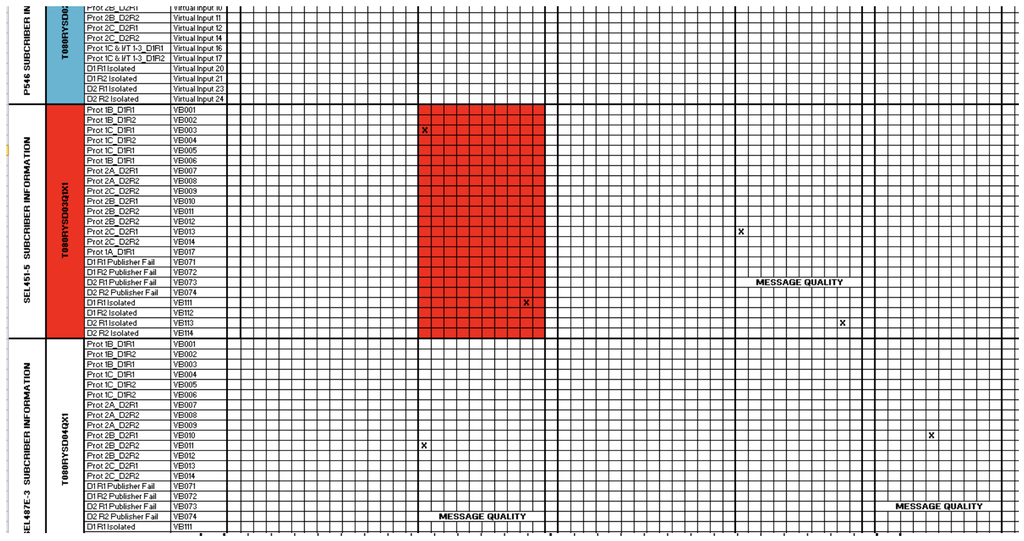 Fig. 3. Tables, describing IEC 61850 communications, either manually generated by PAC designers or automatically generated by configuration tools.
SCL files validation
Validation is a basic and mandatory step in verification and analysis of SCL files. As mentioned, the syntax and structure of SCL files is determined by the SCL schema given in IEC 61850. The SCL schema is an integral part of the IEC 61850 standard and is distributed by the International Electrotechnical Commission (IEC) along with the standard as a set of XSD files that are used for validation. In this case, it is worth making a few comments:
- Currently, there are three versions of the SCL schema that can be used for validation: edition 1, 2 and 2.1 schemas of the IEC 61850 standard.
- For edition 2 of the IEC 61850 standard, there are 2 schemes - revisions A and B. At the same time, only one is valid - revision B, however, some versions of configurators may use revision A due to the fact that they were not updated by the manufacturers in a timely manner.
- In some cases, vendors may slightly modify XSD files to align with their internal config files. This, in turn, can lead to interoperability issues.
Taking into account the above, we can conclude that the best option, especially in projects using IEDs from different manufacturers, is to use an independent software tool for validation, which will fix all possible non-conformities with the IEC 61850 standard that may cause an interoperability problem.
Visual analysis of information exchange
As mentioned earlier, SCL files, in particular SCD files, contain data exchange information between IEDs using Sampled Values and GOOSE communication services, down to individual data items (objects or data attributes). This makes it possible to visualize the communication between the IEDs of the project and to discover errors and inconsistencies. The presence of various types of displaying communications (displaying communications between all IEDs of the project, communications only for the selected IED, subscribers to data elements of selected messages, assignments of data elements of messages to internal signals of the IED, etc.) allows you to step-by-step analyze the correctness of the organization of connections, record as differences in the pattern (that is, in a repetitive pattern) communications, and semantic errors (transmission and use of the wrong signals that are required; not using the required signals, etc.). Solutions such as color coding of communication lines depending on the type of communication (GOOSE / Sampled Values), the direction of drawing communication lines interactively during visualization, the ability to display text descriptions for the IED and the transmitted data in the user's language (if available in the SCD file) simplifies analysis of information exchange. An example of visualization according to the described format is shown in Figures 4-6.
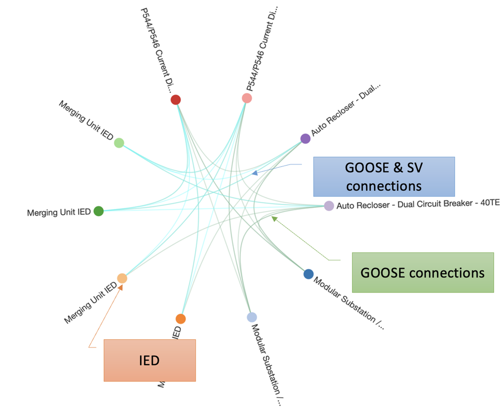 Fig. 4. Visualization of SCD file in general.
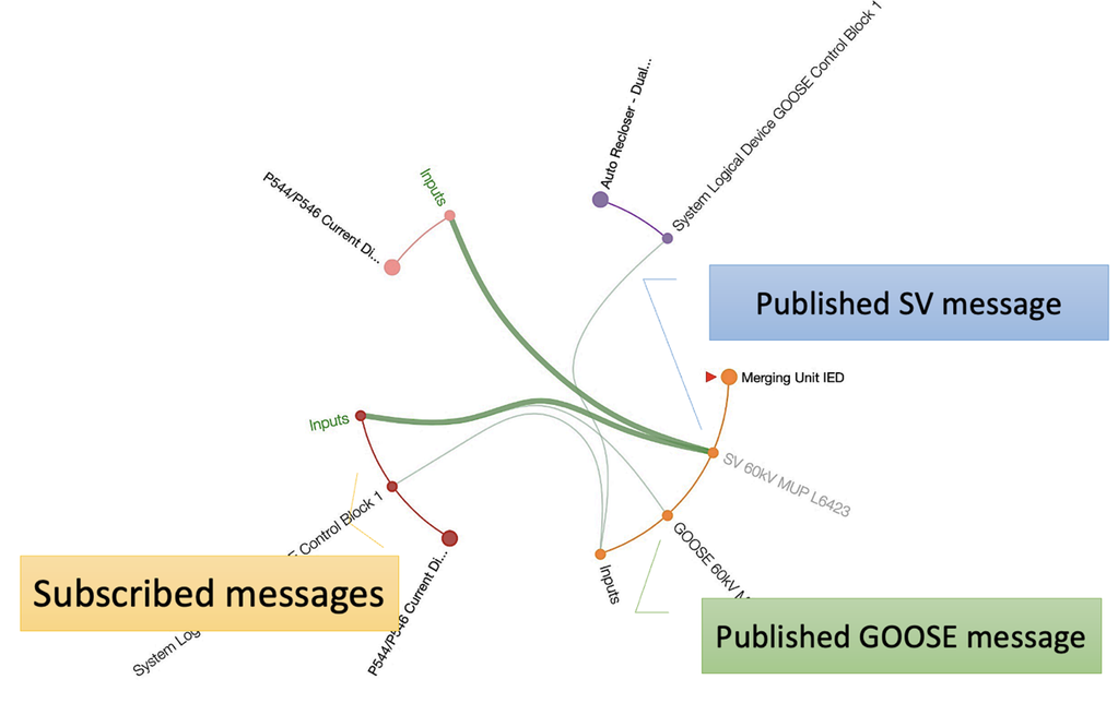 Fig. 5. Visualization of information exchange for one of the IEDs of the project.
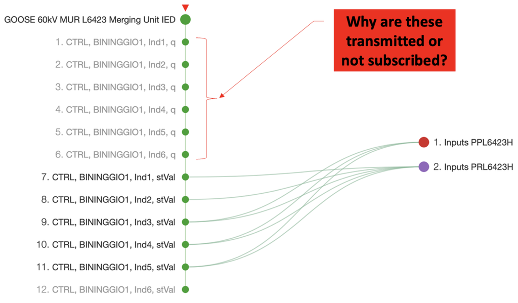 Fig. 6. Analysis of signal composition in messages and their assignments to virtual inputs in subscriber IEDs.
In addition to GOOSE and Sampled Values communications, visualized on the basis of SCD file, the visualization and interpretation of Reporting settings can also be done (Fig. 7).
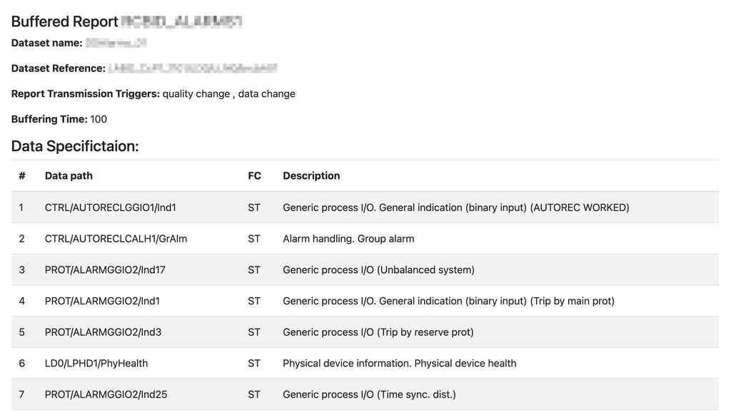 Fig. 7. IEC 61850 Reporting documentation, generated on the basis of SCD file.
Automatic analysis of SCD files
Despite the fact that visualization provides an opportunity to identify errors made in the development of an SCD file, the human factor in such an analysis remains significant, which means there is still a possibility of missing errors, in particular when considering large projects. For this reason, it is extremely important to have the functionality to automatically analyze SCD files according to predefined algorithms.
List of checks that can be performed in automatic mode:
- GOOSE/SV-message has no subscriptions.
- Datasets contain items that are not subscribed to.
- Subscriptions to non-existent data items.
- Quality attributes are either not transmitted or not subscribed to.
- GOOSE/SV-messages have identical destination MAC addresses.
- and etc.
The following subsections discuss in detail each of the listed checks, as well as their effect on the functioning of the system. Sample report of such automated analysis is presented in Fig. 8.
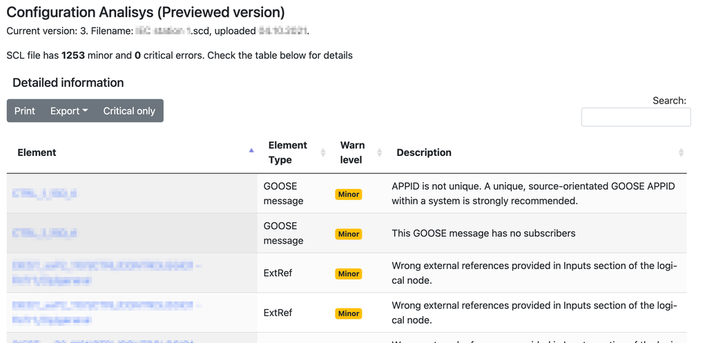 Fig. 8. Sample report of SCD file automated analysis.
GOOSE/SV message has no subscribers
There are two most likely reasons for the presence of GOOSE/SV messages in a project that do not have subscribers:
- The factory configuration of the IED included preconfigured message control blocks that were either not deleted or were not reconfigured to match the design.
- Either the subscriber IED is missing in the project, or the existing IED in the project does not have a subscription (which is actually required).
In the first case, in the presence of a large number of such messages, the network can be overloaded and this can lead either to an increase in information exchange delays or to information exchange failures (loss of messages). In the second case, when either the subscriber IED is missing or the existing IED is not subscribed, this is a configuration error. This error can lead to incorrect operation of the relay protection and automation functions and the automated process control system.
Message datasets contain items that are not subscribed to
Having datasets in a project that include items that are not subscribed to is very similar to when messages are not subscribed. The possible reasons for this situation are as follows:
- The datasets have been preconfigured by the IED manufacturer and have not been changed during system configuration.
- The required subscription is missing.
The first situation may not have a negative effect on the functioning of the system, but the messages will be larger and the times for their transmission over the network and processing of the IED may increase. In practice, the authors came across projects with datasets that included 90 items, only 3 of which were subscribed to. The second situation is an error that can lead to incorrect functioning of relay protection and automation equipment and process control systems, and requires mandatory correction.
Subscriptions to non-existent data items
The presence of subscriptions (references) to non-existent elements in the project is an error and means that changes have been made to the publisher's configuration. For example, some element of the published message dataset has been deleted and/or replaced with a new one, or the message transmission control block has been deleted or changed. This can happen after modifying the publisher IED configuration. Often the occurrence of this error also leads to the appearance of the previously described errors (GOOSE/SV-message has no subscribers and/or the dataset contains elements that are not subscribed to). The indicated error can lead to incorrect functioning of the relay protection and automation complexes and the automated process control system and requires correction.
Quality attributes are either not transmitted or not subscribed to
Quality attributes are an important data element for IEC 61850 systems. The Validity attribute as part of the quality attribute can be used in relay protection algorithms to prevent malfunctioning under conditions of poor signal quality (q.validity = invalid/questionable) and in case of communication failures. In addition, the quality attribute plays an important role in the operation of PAC - in the absence of a quality attribute in the published messages, it is impossible to perform maintenance test of PAC systems in operation.
Practical experience
One of our customers implemented five digital substations with different scale of IEC 61850 usage: three substations have been designed according to the III architecture (using the MMS protocol to integrate the relay protection and automation devices into a single APCS system, using the GOOSE protocol for fast information transfer between bay-level devices (relay protection and automation devices) and information transfer between protection and automation devices and station control units (SCU), as well as the use of the Sampled Values protocol for the transmission of measurement data of currents and voltages from MU devices) and 2 have been designed designed according to architecture II (using the MMS protocol for the integration of the relay protection and automation devices into a single APCS system, the use of the GOOSE protocol for fast transfer of information between devices of the bay level (relay protection and automation devices and control systems) and the transfer of information between protection and automation devices and SCU). During the analysis of 5 projects of digital substations, a number of typical errors in SCL files (SSD, SCD) were identified, which carry both general requirements for file formatting, to further simplify work with it, including the operating personnel, and a number of serious shortcomings in terms of the logic of operation of relay protection and automation devices, failure to eliminate which at the stage of project analysis would lead to the need to change the SCD file at the stage of commissioning and thus delays of commissioning. List of errors identified during the examination of visualized SSD files by specialists in relay protection and automation and process control systems:
- The dispatching names of the primary equipment at bay level are incorrect or missing.
- Incorrect logical node classes are used
- The composition of logical nodes does not meet the stated requirements.
- The bays have the same designations.
The list of errors revealed during the review of the visualized SCD files by the specialists of relay protection and automation and process control systems:
- SV-streams are not described or not fully described.
- SV-configuration is incorrect (smvID is the same for all devices);
- The file does not contain GOOSE messages from relay protection devices, including breaker failure, reverse blocking and busbar transfer signals.
- Identical IP-addresses of devices.
The most significant identified errors include:
- The 10 kV feeder protection of the T-1 busbar erroneously trips the T-2 transformer.
- The 10 kV incomer feeder protection does not subscribe to tie breaker and feeder GOOSE messages.
- T-1 SCU is subscribed to trip signals of the T-2 main protection.
- Fault recorder subscribes to signals from the relay protection and automation devices, but not from the SCU, that directly gets signals of the circuit breaker position.
- When designing multivendor digital substations, it was revealed that the APPID of some devices does not correspond to the ranges stated in the user manual.
- SCD file contains PAC devices not included in the substation project.
- With the phased commissioning of the 110 kV substation, the generation of SV-streams with measurements from the 110 kV VTs of sections 1 and 2 at the first stages, was planned to carry out by line MUs until the installation of the 110 kV VTs of sections 1 and 2. When analysing the SCD files of the second phase of commissioning it was discovered that the SV-stream for 110 kV VTs was not reconfigured at the time of installation of the 110 kV VT MUs.
- When examining the SCL files, it was also repeatedly revealed that the PCS signals (the signals transferred to upper levels of PCS) did not correspond to the specified lists in the design and detailed design documentation;
Identification of errors in SCL files related to the interconnection between IEDs from different manufacturers allows the configuration developer, if necessary, to contact the manufacturers for clarification. Errors associated with incorrect logic of relay protection can be detected only at the last stages of commissioning when testing the operation of relay protection and automation devices on switching devices. All errors identified at the commissioning stage shall be solved on-site, which results in a delay of the commissioning.
Conclusions
Verification of electronic project documentation in SCD file format using specialized tools allows you to detect errors in the communication parameters of the IED, as well as errors in information exchange via GOOSE, Sampled Values and Reports at the design stages and, as a result, ensure the most efficient and timely execution of commissioning. In addition, the presence of the correct SCD file will allow you to fully solve the following tasks:
- Use the SCD file for the subsequent reconstruction and modernization of the system.
- Use the SCD file for IED maintenance and inspection procedures using third-party test-sets and software.
- Apply monitoring and diagnostic systems for IEC 61850 communications.
- Apply cyber security monitoring systems.
The software that was described in this paper and which is widely used by utilities, implementing digital substations, is Tekvel Park. Please, contact Tekvel for further details.


