
Software Based Centralized Protection: commissioning experience
In 2018 Tekvel signed several contracts to commission centralized protection system based on servers and independent software. In this article we would like to share our experience and discuss some of the problems, that might require special attention from utilities on the way to mass deployment of centralized PAC systems.
There have already been introduced a number of concepts of centralized systems starting from devices capable of protecting multiple feeders, up to fully centralized systems capable of handling of the whole substation protection and automation in a single high-performance server. Some of the introduced systems are tied to specific hardware, while others might run on independent platforms.
In our case we have been dealing with the following architecture of the system:
- ISAS is hardware-independent (i.e. it might be running an almost any 86_64 arch machine).
- ISAS runs under Linux OS with special real-time kernel patches.
- ISAS allows multiple system architectures from fully decentralized (i.e. independent instances of the software running on independent servers) to fully centralized (i.e. one server is running one instance of the software implementing functions for all bays of a substation) as shown in Figure 1.
- ISAS architecture allows redundant schemes where multiple servers back-up each other.
- The configuration of ISAS is 99 percent based on the SCD file, that fully describes the whole PAC system, including protection settings.
- Monitoring and control operations are performed via panel PC HMI(s) also fully configurable with SCL-like files and communicating to ISAS servers via MMS.
- SCADA system (if required) is connected to ISAS servers via MMS as well as HMIs.
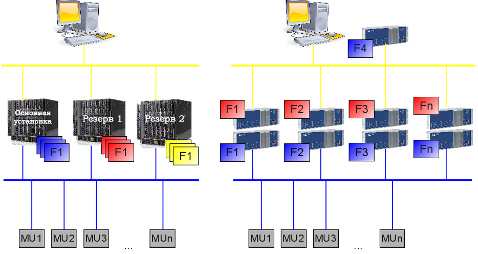 Figure 1. Possible architectures of ISAS systems.
Although different architectures are supported by the software, the most common architecture we’ve seen in real applications is centralization of most functions and using back-up server for redundancy. Also due to local regulations a separate server might be required for Metering, Fault Recording, etc. (Figure 2).
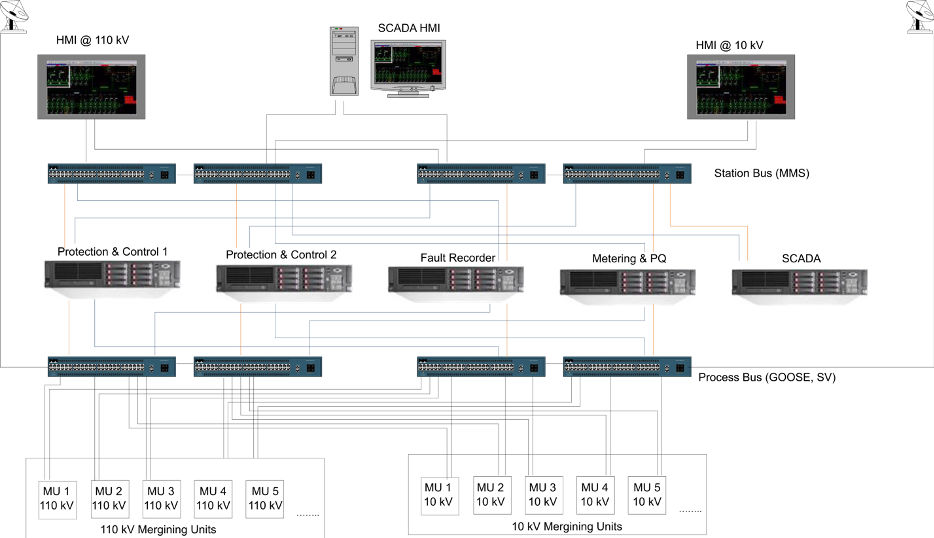 Figure 2. Common architecture of ISAS system.
We have been commissioning 3 projects with ISAS (fully or partially):
- 110/10 kV substation fully running PAC for the whole substation in two servers with ISAS software with conventional transformer differential used as backup protection (referred as Project 1).
- 110/35/10 kV substation with multiple ISAS servers. ISAS is used there as the only control system, while protection is fully duplicated by conventional hard-wired relays (Project 2).
- 35 kV shunt reactor protection at 220 kV substation using ISAS (Project 3).
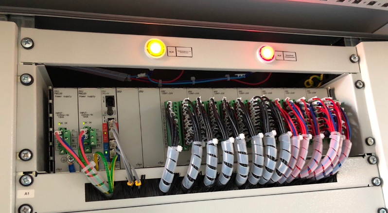 Figure 3. Combined MU and SCU IEDs.
In terms of general approaches all of these three projects had much in common:
- Combined SAMU+SCU devices (hereinafter referred as field devices) were installed in the switchyard or in secondary equipment compartment of the switchgear (see Figure 3). Field devices are capable of processing binary inputs and analog current and voltage signals and publishing GOOSE and SV messages respectively for each kind of signal. They are also capable of subscribing to GOOSE messages and switching binary outputs based on the data in the GOOSE message.
- Notable that field devices used in those projects had modular design allowing same approach for different bays (i.e. different number of signal).
- For 110 kV bays multiple (two) field devices were used per each bay to ensure reliability of the system. Both field devices were subscribing to data from both main and backup servers eliminating single point of failure.
- For 10 kV bays single field device is used.
- Process bus network has a double-star topology with PRP redundancy protocol. For smaller projects single ethernet switch is used per each PRP LAN A/B. For larger project multiple daisy-chained switches might be used within each PRP LAN A/B.
- Time synchronization for process bus network devices is provided using PTPv2 time synch protocol with time servers integrated in Ethernet switches.
- Multiple panel PC HMIs were used in larger projects, each providing monitoring and control functions for each voltage level. Typically, 10 kV HMIs were installed near the 10 kV switchgear, while 110 kV HMIs installed in the control room.
- In our case there were no projects where ISAS system was used for metering or PQ monitoring. Although technically it was possible, it has never been implemented due to regulation issues.
Each project also had some specifics introduced by huge differences in the number of bays which resulted in different computation power required. In Project 1 and Project 3 there were only 2 servers (main and back-up) running ISAS software. While in Project 2 there were 6 servers: 4 running protection functions and 2 running automation and control functions (see Figure 4). There were also differences in hardware used: in Project 1 and 3 HPE Proliant servers were running ISAS software, while in Project 2 ISAS software was deployed on DELL servers. There were also differences in network interface adapters (NIC) installed in servers (that turned out to be important.)
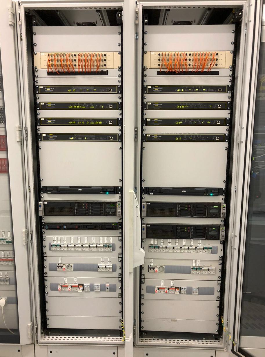 Figure 4. Project 4 server racks.
Commissioning Experience
When starting with commissioning of ISAS projects we had quite a vast experience with commissioning of different IEC 61850-enabled systems based on regular IEDs, so we felt ourselves quite comfortable in configuration of all of IEC 61850 communication protocols: GOOSE, SV, MMS. We also had experience in substation LAN design and configuration (including traffic filtering which becomes crucial in such kind of projects). Finally, we also had experience with PTPv2 systems commissioning and troubleshooting. Making it short: to the point when we have stated commissioning of ISAS projects we were absolutely confident in our skills to commission any IEC 61850 system.
Commissioning of ISAS system might be split into the following parts:
- Initial configuration of servers including installation of ISAS software environment.
- Configuration of the system using SCD file including deployment of the configuration to the servers.
- Configuration of MU and SCU devices.
- Adjacent systems configuration: LAN & Time Sync.
- Configuration of panel PC HMIs.
- Configuration of external SCADA system (if required).
Initial Server Configuration and ISAS installation
Major difference between what we usually have while commissioning standard IEDs compared to commissioning of software-based protection is that in the second case the hardware is initially blank and usually shipped independently of the software. In our case the contractor has purchased servers for ISAS deployment independently of the software, i.e. servers were blank when we started the commissioning. So, the first step required was to install Linux OS with ISAS software to the server and run at least a simple demo-project to make sure the system is working and ready for deployment of full configuration. We won’t go into all issues we have had, but we’ll try to summarize them briefly:
- The ISAS software due to its real-time operation requirement and high CPU load includes so-called kernel modules that become deeply integrated into Linux and are strongly dependent on the version of Linux installed. Thus, we were tied to a specific Linux kernel version as we were provided with a precompiled binary library of ISAS.
- The hardware that we had in the project was quite modern and it turned out that some modules (including modern network interfaces) were not supported by the provided Linux kernel. So, we had to compile drivers for NIC ourselves from source-code files proved by the NIC manufacturer. Additionally, as hardware platforms in each project were different, some project-specific configurations were required. At this stage we had to ask for support from developers a bit and to involve our programmers when driver compilation was required
- Many software modules for Linux are distributed as packages using package managers (such as apt, yum, rpm etc.). When some module is required administrator might install it using a simple command line yum install <
>. When processing this command package manager checks for required dependencies and automatically installs them if they are not present in the system. Package manager is aware of kernel version and installs proper version of the package compatible with kernel, so administrators usually don’t have to take care of that. Normally when this happens during server configuration in the office/lab or datacenter environment packages are downloaded from remote repositories via Internet-connection, so no additional efforts are usually required from the administrator. However, in case of substation environment internet connection might be unavailable or limited (especially for remote high-voltage substations) or restricted (due to cyber-security considerations). This requires additional efforts as administrator must have local copies of the repositories for specific kernel version, which in most cases is almost impossible and finally would require administrator to make installation in multiple steps. Finally, when all required packages and modules have been installed and ISAS was successfully installed on the servers, deployment of test project was required. At this stage in one project we have discovered that GOOSE messages from ISAS software were transmitted with the wrong EtherType (0x0000 instead of 0x88b8). It required an additional couple days of investigations resulting in recompilation of NIC drivers with different parameters.
The above described steps took us almost as long as three months in total until we were ready to deploy ISAS software on nearly any hardware. In our case we had a group of 3 highly-qualified engineers and one senior programmer solving this task. From now on we are quite sure that it is going to be much easier for us and it won’t take that much time. However, it is important to note that in case of hardware replacement these operations shall be required again. And at that moment the utility would either require its own staff to handle all of these operations or hire a company with required skills.
ISAS System Configuration
As it has already been mentioned above, ISAS system is almost fully configured using SCD file, which makes it very convenient for engineers feeling comfortable with SCL files and IEC 61850 data models. Each function of ISAS is represented by a logical node, and all interconnections between functions (including communications between functions inside single IED) are described by InRef data objects of the logical node receiving data. The main drawback of system configuration of ISAS was absence of proper configuration tool. The system uses some proprietary syntax in SCL-files which prevented us from using third-party SCTs, while no configuration tool was provided by vendor. Thus, all the configuration has been created completely manually (fortunately we had a configuration for another project, that we used as the template). Engineers who have at least once tried to create or edit full system configuration manually would be able to assess the problem: final SCD file for the Project 2 counted over 470’000 lines of text (see Figure 5). We think that these mentioned configuration issues are temporary, and they would be solved in the nearest future. At least elimination of proprietary syntax in the configuration would allow using third-party configuration tools, which would make the job much easier.
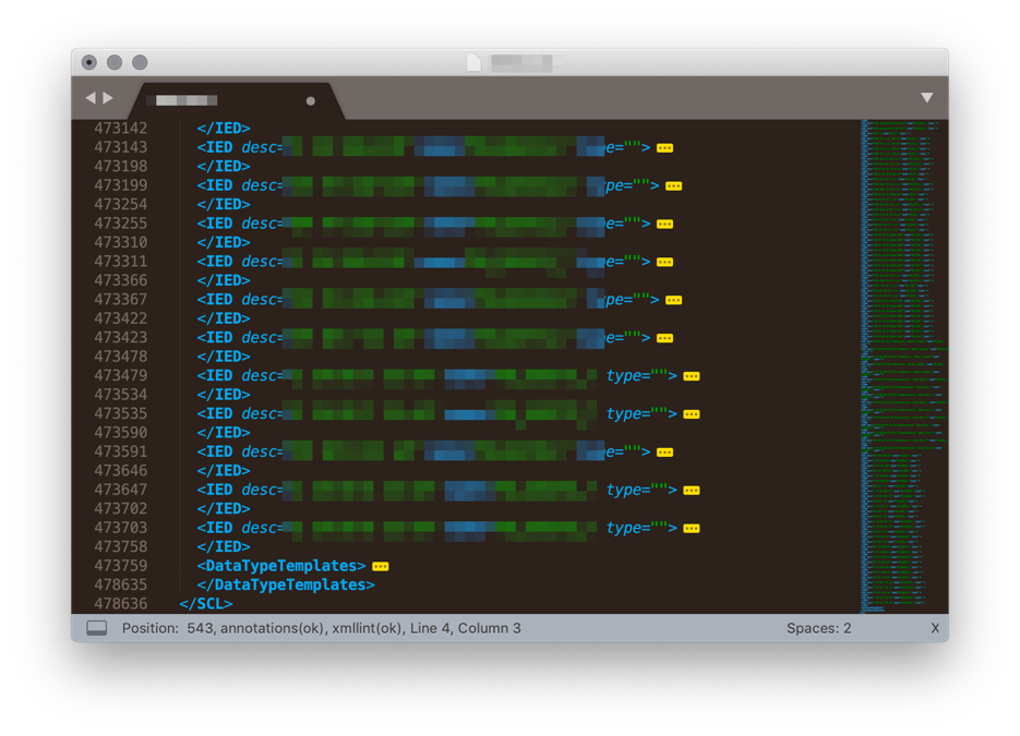 Figure 5. ISAS SCD configuration file.
Another important thing related to the configuration files is their management. As the SCD file becomes a single container of the whole configuration of the substation, it then requires a special care. In our case we have decided to manage the system configuration in the same way as source codes, storing all the versions and tracking the differences between them. We have faced all benefits of this approach when once the customer, making some changes to configuration, has deployed an outdated version of the SCD (that they stored on the USB stick), which resulted in badly degraded performance of the system. For the purpose of configuration version control we have used our Tekvel Park system that analyzes the SCL configuration and shows differences compared to the previous version. As it has been already mentioned before, the SCD file is almost 99% of all of the configuration of ISAS. However, this 1% left is also very important and is related to server resource allocation which plays a critical role in system reliability. The configuration has to be allocated on hardware in the most optimal way, providing real-time processing without interruptions and delay. In case of the system we were commissioning, we had to select the allocation of virtual IEDs on CPU cores manually. We believe that in mass deployment of such systems this configuration might be made automatically based on known resource usage for each logical node inside virtual IED.
Configuration of MU and SCU IEDs
Although in this article we put this stage after server configuration, in fact this stage is integrated in the previous step, because MU and SCU configurations shall also be described by the SCD file in order to make required subscriptions to GOOSE and SV messages. There are almost no specifics of MU and SCU configuration in this system compared to regular IEC 61850 systems and is largely dependent on the IEDs used as MU and SCU. Communications between MUs/SCUs and ISAS were using GOOSE and Sampled Values only, i.e. no MMS protocol was used at process bus level.
LAN and Time Sync Configuration
We have included Time Synchronization together with LAN (i.e. Ethernet switches) configuration because in case of described projects, Ethernet switches were used as PTP Grandmaster Clocks and PTP configuration has been required during switches configuration. Time synchronization configuration itself does not have any specifics compared to projects with decentralized IEDs subscribing to SV messages. The configuration of the Ethernet switches however has some specifics. First of all, the total number of SV streams (e.g. 192 in Project 2) requires special care, as 100 Mbps network is not capable of passing over such an amount of traffic. Moreover, if this amount of traffic would not be filtered and would reach the edge port of the switch (i.e. the port connected to the IED: MU or SCU) this would in most cases lead to denial of service of the IED, so that the IED would not be able to perform it’s communication functions. On the other hand, the servers running ISAS have very high-performance network interfaces with the throughput up to 40 Gbps and the design of ISAS software allows reception of a huge amount of SV streams through single NIC port. In the described case Ethernet switches become some kind of one-way gates: allowing SV traffic to come inside by limiting it to go outside through the port connected to server. Technically this is achieved by setting separate VLAN ID for each SV stream and then restricting them on all of the switch ports except for server-port. However, the GOOSE messages shall not be restricted, so separate VLAN is required for them. The only issue left here was network troubleshooting, related to SV messages. The amount of SV traffic going from the switch to the server was so large that is was absolutely impossible to monitor it using any software-based tools running on regular PCs. Also, the test-set we tried for this purpose didn’t fit as it was detecting frame-losses, that turned out to be dropped by the test-set itself. In our case we again had to use Tekvel Park with specially designed high-performance network monitoring module, capable of handling of up to 100 SV streams simultaneously, which allowed us not to lose time on reconnections and reconfigurations of the monitoring system during commissioning.
Configuration of Panel PC HMIs
As there is no physical IEDs in ISAS-based system, located in the control room, the monitoring and control operation must be performed through SCADA-system or through the specially installed panel PCs with touch screens (see Figure 6). This panel PCs running HMI software module of ISAS provide a set of capabilities usually expected from the regular IED HMI: status signals, measurements and alarms display, control operations (including primary apparatus control), settings and setting group management and log display. The HMI communicates to ISAS servers via MMS.
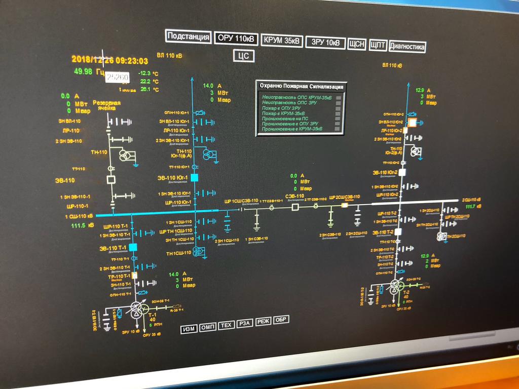 Figure 6. Panel PC HMI.
The configuration of HMI itself had very much in common with ISAS server configuration:
- We had to prepare the system: install Linux and install HMI libraries.
- Configure the HMI using configuration file.
HMI configuration was rather difficult - again because the tools provided for configuration were not mature enough, so we had to create the configuration mostly manually. However, we expect that it might become much easier in the future, because the HMI configuration is based on Substation section of the SCD file, so with the evolution of the configuration tools this job may become highly automated.
Conclusions
As a result of our work we have been able to successfully commission and based on our experience we have made the following conclusions related to software-based protection:
- Software based end especially centralized protection is a very promising technology, and there is a good proof-of-concept for that.
- Software-based protection independent of the hardware allows ultimate flexibility and opens interesting possibilities of using high-performance servers thus reducing costs compared to conventional IED-based approach.
- Both commissioning and maintenance of software-based PAC system differs a lot from regular IED-based PAC as it requires Linux server administration skills which is completely different from what PAC commissioning requires today.
- As configuration files for the system start playing the crucial role in system performance, they shall be treated with special care: storage and version management become mandatory.
- Commercial servers usually have much smaller life cycle compared to IEDs, which would require server replacements in some years. This issue has to be investigated additionally, as updated hardware might be incompatible with older software.
- The maturity of technology we’ve been dealing with still doesn’t allow mass implementation of such kind of systems, as it requires much more knowledge and experience from all the parties: from design to maintenance.
- We expect that advancements in configuration tools together with implementation of application profiles would significantly improve the process of system configuration of software-based PAC systems.
- Implementation of software-based PAC systems would likely require utilities to reorganize protection and control departments if routine maintenance of this equipment shall be performed by utility staff.


